INSTALLATION
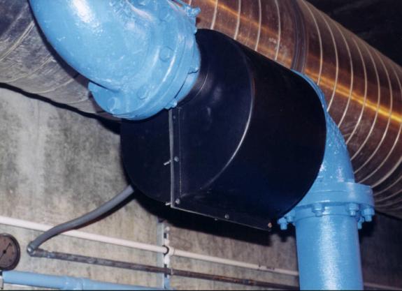
ED 2000 Anti-Fouling System consists of an electronic control unit, a pre-wrapped solenoid sheet and a "clam-shell" ABS plastic enclosure. The clamshell enclosure is fitted over the condenser supply (and return) pipe in either a vertical or horizontal position prior to the chiller. The pre-wrapped solenoid sheet inside the enclosure is made of a single-stranded 14-gauge wire. The control box is a NEMA 12 rated enclosure.
Figure
1
LOCATION
The
best place to install the ED 2000 coil is within 50 feet of pipe length prior
to the chiller or heat exchanger that is to be treated. This distance can include valves, 90° elbows
or 180° turns. One coil is mounted on
the condenser or heat exchanger supply line.
Coils should be placed:
§
On the discharge
side of the pump
§
Prior to the heat
transfer site (chiller, tower or heat exchanger) that is to be treated
§
Within 50 feet
from the control unit
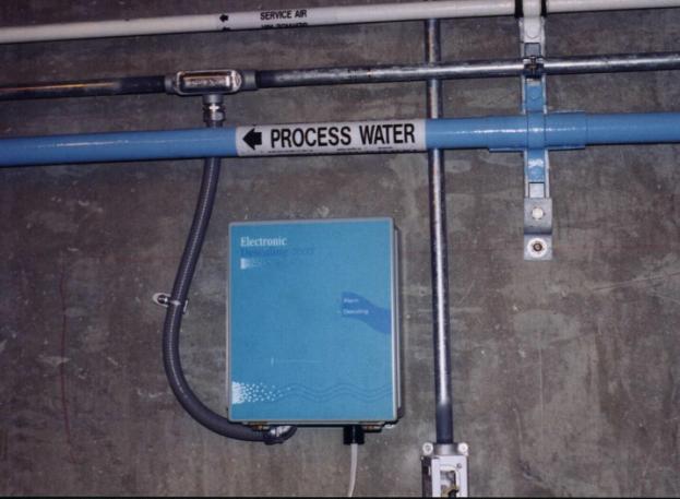
1. Mount the control box within 50 feet from where the coils will be
placed.
2. The power supply should be run inside conduit. The low voltage cable can also be run inside conduit, depending on local electrical codes. Please have a licensed electrician direct wire the power supply.
3. Connect the power of the ED 2000 Anti-Fouling unit to a power
source outlet (110V AC, 50-60Hz, 1.5 Amps).
Do not reverse the polarity of
the power cable as this may damage the unit. Power may continuously
run. It is not required to turn off the
system at any time. Power consumption
is approximately 150 watts.
4. Open
up the clamshell enclosure (the pre-wrapped coil is already fitted inside) and
fit it around the pipe.
Do
not permanently close the enclosure until the wiring is complete.
5.
Run the wire from the control box to the clamshell enclosure. If additional distance is required, please
contact the factory, as it is not suggested to place the coil more than fifty
feet from the control box. The shorter
the distance between the control unit and the coils, the better. Please remove any excess cable.
6. Connect
the second coil in parallel. The two coils may be connected inside the
clamshell enclosures or you may use a separate electrical junction or utility
box mounted externally on or near the clamshell enclosure. The control box is designed to accept only
one set of wiring therefore when two or three clamshell enclosures are used an
electrical junction/utility box is required.
7. Make sure the green light is on. The red, ALARM light indicates that there is an open circuit - a break in the flow of current. If a red light is on, check the coil connections.
8. Testing: A test may be
performed to insure the unit is operating under optimal conditions. Measure the amperage of the coil connections
with a multi-meter. Output voltage may
not be measured because it is a switching circuitry. A measure of amperage and frequency should indicate approximately
4.5 Amps and 0.450 kHz with the multi-meter connected in series. (AC setting
because of square wave current). The power is converted from 110 VAC, 1.5 Amps
to 24VDC, 6 Amps. The unit is tested at
the factory so this step is not mandatory.
9. If you have any questions regarding this installation, please
contact support at (888) 474-2933 or info@ed2000.net.